For the past week, I have been looking into assembler programming, specifically for the AVR series. I have really been enjoying Gerhard Schmidt's AVR assembler tutorial, which seems very thorough.

I tried to implement the blink example, and maybe went a little overboard. The usual reasons for using assembler programming instead of C is optimizing timing and/or program size. My results: the final program is 44 bytes in binary form, and each led change is (or should be) exactly 16 million cycles, which is one second on a 16MHz clock. The program can of course be modified for other clock speeds and blinking intervals - up to 65535 millisecond per blink.

This is compared to the arduino blink example, which is 1084 bytes and precise only to the millisecond (If I remember correctly).

I am totally new in assembler programming, and if you find a mistake, please tell me!

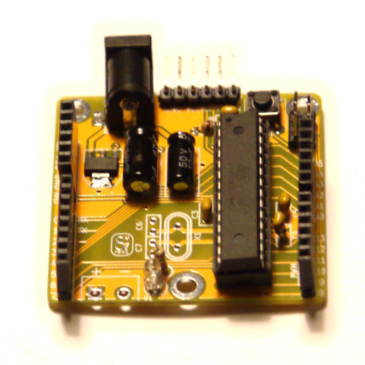
I have ordered some attiny13a's, and made some small development boards for them. But more on that later!

The code:

; My first piece of assembler code. It is made to mimic the blink
; example from the Arduino environment. The arduino example compiles
; to around 1Kb - this is 44 bytes. And should be very 
; precise in the timing.
.nolist;
.include "m88def.inc";
.list;


; SETTING CLOCK SPEED - currently at 16 MHz
.equ clockCyclesPerMilliSecond = 16*1000
; The delay to put between blinks in milliseconds
.equ delayMilliseconds = 1000
; The direction register, the port and the bit to set the pin of the
; LED to flash
; Currently at PB5 (Arduino pin 13)
.equ DDR = DDRB
.equ PORT = PORTB
.equ BIT = 5

; SETTING UP REGISTERS
.DEF my_register = R16

; Not sure if this is needed... It works without it.
rjmp    setup

; setup
setup:
    SBI     DDR,BIT         ; Set pin to output

loop:
    sbi     PORT,BIT        ; 2 cycles - set pin HIGH
    rcall   Delay           ; 3 cycles (the call itself) 
    cbi     PORT,BIT        ; 2 cycles - set pin LOW
    rcall   Delay           ; 3 cycles (the call itself)
    rjmp    loop            ; 2 cycles (the jump itself) - repeat

Delay:
    nop
    ; Delay consists of two loops - the inner loop loops for a
    ; millisecond, the outer counts the number of milliseconds-
    ; From every inner loop, there is subtracted the number of 
    ; cycles to complete the outer loop (8). From the first time, there
    ; is also subtracted the number of cycles to call, setup and return
    ; from the subroutine as well as the cycles for switching the pin,
    ; half of the rjmp command and the nop in the start of this function

    ; inner loop : 4 cycles
    ; outer loop : 8 cycles
    ; pin switching, calling, returning and looping : 16 cycles

    ; Since precision is made by cutting the number of times the
    ; inner loop runs, it is important that the number of cycles
    ; in the outer loop and the one-time-fluff is divisble by 4.

    ldi     ZH,HIGH((clockCyclesPerMilliSecond-8-16)/4)
    ldi     ZL,LOW((clockCyclesPerMilliSecond-8-16)/4)
    ; A lot of nops and grief could be saved by only supporting a 
    ; maximum of 255 millisecond delay.
    ldi     YL,LOW(delayMilliseconds)
    ldi     YH,HIGH(delayMilliseconds)

    delayloop:
            sbiw    ZL, 1       ; 2 cycles
            brne    delayloop   ; 2 cycles

        sbiw    YL,1                                     ; 2 cycles
        ldi     ZH,HIGH((clockCyclesPerMilliSecond-8)/4) ; 1 cycle
        ldi     ZL,LOW((clockCyclesPerMilliSecond-8)/4)  ; 1 cycle
        nop ; added to make a number of cycles divisible by 4 1 cycle  
        nop ; added to make a number of cycles divisble by 4  1 cycle
        brne    delayloop                                ; 2 cycles

    nop ; added to make a number of cycles divisible by 4 ; 1 cycle
    ret ;                                                   3 cycles

This post has been a long time coming, but I wanted to write it up at a time when I had the time to go into some detail with regards to the choices I had to make, designing the Eightuino as cheaply as possible. The things in this post are not innovative, nor can the be considered rocket science. They are mainly small tips, which I have discovered doing this project.

To sum it up, the cost of a board can be split into three parts:

  • The choice of functionality
  • The price of components
  • The price of the PCB

Actually, there is a fourth, the manufacture cost of the boards, but seeing as this is a DIY product, I will not treat this cost. The more of a challenge it is, the more fun you get to have, right?

Functionality

If you cut an arduino down to the basics you basically have an Atmel Atmega microcontoller and some stuff to make it work and some other stuff to talk to it.

You want to do both, but you can choose the first class ticket, and you can choose the more economic route. The equivalent of cheating your way along with a freight train is having a microcontroller on a breadboard, three AA batteries and a pullup resistor on reset and that's about it. I have tried to seek the middle ground

I have opted to INCLUDE the following:

  • Pull-up resistor on the reset pin AND a reset button
  • A voltage regulator for provding a known, steady voltage
  • Decoupling capacitors to smooth surges in the power supply
  • AVR 6-pin programming header
  • A pin row for connecting a USB 2 TTL serial interface
  • Optional: A crystal oscillator and load capacitors

I have opted to EXCLUDE the following: * Dual power supply. The Arduino have dual supply, that is both 3.3v and 5v. Mine only have one voltage regulator * Built in USB interface.

The arduino and clones usually uses either a FTDI USB interface IC or an Atmega8u2 (or Atmega16u2) IC for the USB interface these chips alone costs between 10 and 30 DKK - which touches the total materials cost for the entire board. When you have more than one board, you might as well use an external programmer and/or an external USB serial interface. I already have an AVR programmer, so that settles it for me.

Price of components

When buying components, it is certainly not that hard to choose component. You just find something that has the right qualities - and then you just order it from Mouser or Digikey. Okay, this is simplified and actually not true at all, but for simple project such as this, it would be relatively easy.

I have opted to try and find parts that is cheaply available from China, that is available from Ebay, AliExpress or DealExtreme.

An example was the voltage regulator. Because I wanted to have the option of going either 3.3V or 5V, I could not use the classic 7805. So I found the LM1117. But since the through hole version was $0.50, it was kind of expensive. But the SMD version (SOT-223) was only $0.05, so I decided to be adventurous and try my first SMD part - It turned out that SOT-223 is an enormous SMD part and not hard at all to solder, so the decision payed off, and I saved almost 3 Royal Danish Crowns on the voltage regulator alone!

Another example is the Atmega microcontroller. If you don't need the 32Kb of memory (and most of the time I do not) or the 16MHz clock (and most of the time I do not), you can use the Atmega8L (8Kb, 8MHz) as a perfectly good replacement for the ususal Atmega328P. The Atmega8L is usually about $1 compared to the about $2.50 for the Atmgea328P.

The pinouts of the Atmega8L and Atmega328P are the same, so the board can be used for both, should the need for speed show its face.

Price of the PCB

Getting a PCB made is not expensive at all these days, and there are several services out there, offering small runs for the price of a pizza including shipping (both the PCBs and the pizza). The common offer is 10pcs PCBs for $10, if the PCB is less than 5x5cm.

So to make the PCBs as cheap as possible, the goal is to stay under 5x5cm. Simple as that!. A 2x3cm costs the same as 5x5cm, feel free to go nuts within the boundaries.

I have tried both IteadStudio and Elecrow, and SeeedStudio is another service provider - they all use the same factory as far as I have gathered. I usually go with Elecrow, because they offer colours other than green without extra costs.

Other manufacturers, such as OSHPark have other price schemes, where you pay by area unit ($5 per square inch), and such smaller is cheaper.

Conclusions

  • Do not go for more functionality than you need
  • Choose a cheaper part, if it can do the job
  • Keep your PCB within the constraints of the manufactures price tiers.

Oh, and a word of warning: when shopping cheap, look out for dodgy vendors. I have 10 1:1 scale models (non-functioning) of the Attiny2313 to prove it.

There have been some comments on Elektronik-forum, suggesting other ways of obtaining a cheap arduino(-clone), instead of doing the work of designing the thing yourself. So I feel that I need to explain myself. To sum it up, it as a matter of a few small adjustments, but mostly the learning experience of designing a board.

I have been suggested these three methods:

  • A chinese clone - basically a 1-to-1 chinese copy
  • The Nanino - one sided home-etchable FTDI-less board
  • The JEENode - A stick-thingy with 868MHz RF data transmission

And these are all good suggestions, although the first one is a bit dodgy, especially when the copies still have the Arduino logo on it, while not being produced anywhere near Italy. In fact, I own two chinese copies, one of the Arduino Leonardo and one of the Arduino Mega.

The nanino is pretty much what I was looking for, except for the pin-spacing issue, which I mentioned in the [previous post]. And I am not currently doing home etching of copper. When I take this up, I will definitely make a try of the Nanino

The JEENode is also great. It has a reasonable pin layout, and the RF thing looks interesting. But I currently need the RF, and the while the slim boards a great for breadboards, I like my shields to have the pins on the sides, not in the middle. They sell empty boards for €5.00, which I may try when I get an idea for an RF project.

So I need something that is cheap (Nanino), have a reasonable pin-spacing (JEENode) and is good for perfboard shields (??). These are my needs for the product itself. So I will make it myself.

I am sure that someone somewhere have built a board that meets my needs (almost) perfectly and probably at a reasonable price. But I am also (mainly) doing this for trying to go through the proces of designing a usable board, and discovering all the small pitfalls, which is not apparently clear when looking at guides on the internet and videos on YouTube.

Stay tuned (still) for the "Designing on a cheap"-post.

In this and the next two posts, I will outline what I understand by the design goals of the Eightuino. The first goal is that it should be "DIY friendly".

Although the Eightuino in this iteration will be almost exclusively through-hole, this is NOT what is meant by DIY-friendly. The hole thing stems from the fact that the otherwise immensively talented people at Arduino made ONE irritating mistake when designing the layout of the Arduino:

On the one side of the board, the gap between the two rows of headers is a non-standard 0.16". This makes it necessary to use special "proto-shields" instead of regular 0.1" perfboard when hacking something on top of it. And protoshields are more expensive than perfboards.

So the Eightuino will definitely have to use a 0.1" pin-spacing. No discussion!

So that is the spacing between the individual pins. But what about the space between rows? Well, seeing as I personally have about 50-60 pieces 5x7cm perfboards lying around, how about I make the Eightuino fit these? They have 18 holes across, making the distance from one side to the other 1.7". So that is now the official row spacing on the Eightuino.

All this do, however, break compatibility with existing Arduino Shields, and an Eightuino User (that is, I) will not be able to share my shield-designs directly with non-eightuino users. Well, the Eightuino main purpose is home DIY use and for hacking together something on a perfboard, not for mass-producing pcb-based shields.

Does this make sense? I think so :-)

I am currently developing my own AVR development, arduino like. I want to make it a industrially made PCB, and I want it I am certainly not the first one doing this (or even in the first thousand), and some would probably say "Niels, this is a totally pointless exercise, why don't you go to something else"

And maybe it is, but who are they to tell me what to do? I have some issues with the arduino in its standard configuration, where the most irritating of these are the downright stupid design decision of a pinspacing incompatible with a standard perforated protoboard. And they are expensive, unless you go with an imported clone.

But I go the idea in this episode of the EEVBlog, where Dave agrees with a viewer, that building a kit is a good learning experience. Mind you, he is probably talking somehting more advanced than yet another Arduino clone, but this has the added advantage of giving me a piece of experimenting equipment that I need.

Design goals:

  • DIY friendly
  • Programmable from the Arduino IDE
  • As cheap as possible.

In the next couple of weeks, I will go through the process of designing the Eigthtuino.

I am currently at my second prototype, which, confusingly, is called the eightuino, rev1. It will take some time before the blog series will reach this far, but here is a spoiler (yes, I now, it is a bit wonky in the construction, that is what you get when you solder with a hangover):

Eightuino Rev1, first look